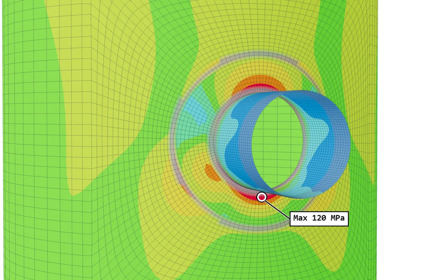
Linearisation splits the stress along a stress classification line into three parts. The membrane part is the average through the wall, the bending part is the straight-line part found from the first moment about the mid-wall, and whatever is left is peak.
This post works one line by hand with round numbers, then shows how FEXLA does the same on a solid model and why its shell model does not need to.
The two integrals
Let x run through the wall along the line, from end a on the inside at x = 0 to end b on the outside at x = t. For one stress component σ(x):
The linearised stress is σm + σb at end a and σm − σb at end b, with a straight line between. The peak at each end is the total stress there minus the linearised value.
The factors are no accident. The first integral is the force per unit length carried by the wall, divided by t. The second integral is the moment per unit length about the mid-wall, and 6/t² turns it into a face stress, the same 6M/t² as for a beam. So the membrane and bending parts are the stresses of a wall that carries the same force and moment, with the stress spread in a straight line.
A worked line
Take a 20 mm wall with five readings along the line, highest at the inside face. The integrals are done with Simpson's rule on the five points, at a spacing h of 5 mm.
There is a check on the arithmetic. At mid-wall the total is 110 MPa and the linearised value 120 MPa, so the peak there is −10 MPa. Across the wall the peak part goes +20, −10, +20: it adds up to no force and no moment. That is what the split means. All the force is in the membrane part, all the moment is in the bending part, and the peak carries neither.
Six components, not one number
A real line has a full stress tensor at each point. Annex 5-A linearises it component by component, in the line's own axes: along the line, through the wall; across it, in the section; and the hoop direction. The membrane part is taken for every component. The bending part is taken only for the components parallel to the wall. The normal stress through the wall and the shears on it get no bending part.
The equivalent stress is taken after that: von Mises by default, as Division 2 has used since its 2007 edition, or Tresca stress intensity for earlier editions. It is worked out for the membrane tensor, for the membrane-plus-bending tensor at each end, and for the total at each end. FEXLA linearises the components first and takes the equivalent stress after, never the other way round.
How FEXLA does it
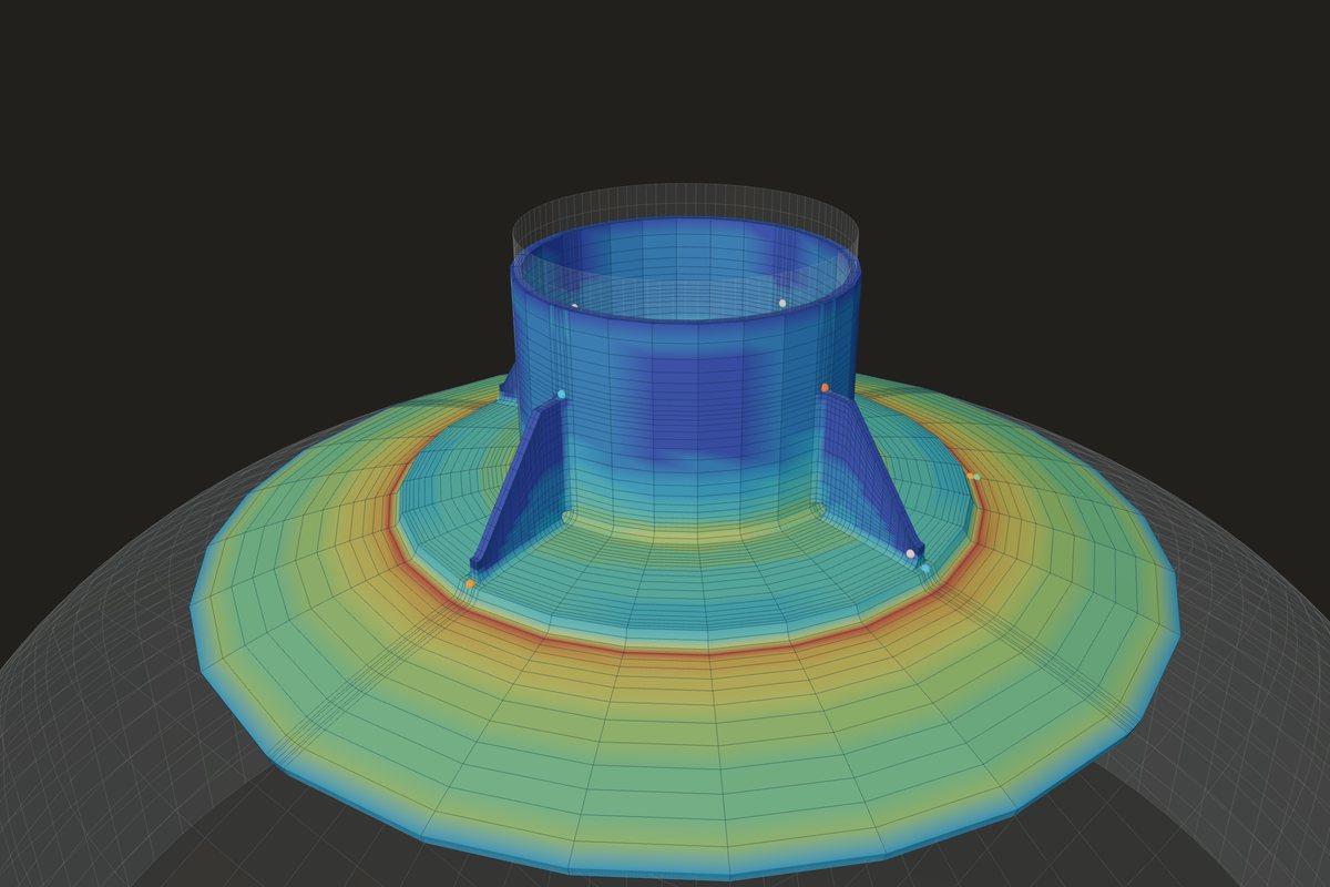
On a solid detail of a junction, modelled in brick elements, the stress tensor is sampled at 41 points along each line from the bricks' nodal stresses, turned into the line's axes, and integrated by Simpson's rule, as in the hand example. A table gives the equivalent membrane, membrane plus bending at both ends and total stress, and a plot shows the total and the linearised stress through the wall.
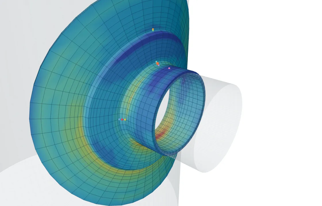
In the shell model the work is already done. The stress through a shell element is a straight line by construction:
So the membrane and bending come out exactly and there is no peak part at all. Along a weld line the model takes the force and moment the elements pass across the line, which gives the membrane and bending there from equilibrium.
Reading the result
A small peak means the stress along the line is close to straight, which is normal away from notches. A large peak means it is far from straight: a corner, a notch, or a line in the wrong place. The membrane and the membrane plus bending go to the primary and secondary checks; the peak part is for fatigue. At a sharp corner of a solid model the total, and so the peak, rises as the mesh is refined, so it is not a number to design with.
Where it stops
- 01Linearisation sorts stress by its shape across the wall, not by its cause. Which category each part belongs to is a separate decision under Table 5.6.
- 02The peak at a sharp corner of a solid model depends on the mesh.
- 03A shell model has no peak part by construction; peak stress at a weld toe needs a solid model or a fatigue method of its own.
- 04The finite-element results are early access and under verification.
Try it in FEXLA
The Nozzle loads card runs the shell model, which reports membrane and bending directly; a solid detail of the junction adds lines linearised as shown here.
Open the cardReferences
- ASME Section VIII Division 2, Part 5: Annex 5-A, 5-A.4.1 (linearisation by stress integration); 5.2.2.1(b), eq. (5.1) (von Mises equivalent stress); Table 5.6.
Method notes this draws on
Next post: The local primary membrane region test (VIII-2 5.2.2.2(b))
Educational article. It explains principles and is not design guidance; follow your governing code and edition.