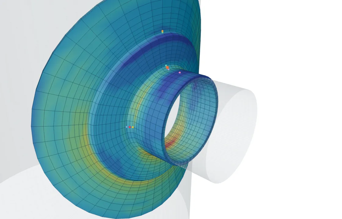
In a shell model the nozzle and the shell meet on one line, the intersection of their mid-surfaces, and that line lies inside the real metal. FEXLA reads the junction stresses at the weld toes instead, half the other wall plus the weld leg away from the line, and plots but does not check the weld zone in between. That gives the membrane and bending stresses a code check needs; the peak stress at the toe notch is not in a shell model at all.
Where the stress is read changes the answer by tens of percent, so it is worth knowing exactly what the report means by a junction stress.
The line where the parts meet
A shell element stands for the wall by its mid-surface. Where a nozzle meets a shell, the two mid-surfaces cross on a curve, and the mesh joins the parts there by sharing nodes. On the shell's side that curve is half a nozzle wall inside the nozzle; on the nozzle's side it is half a shell wall inside the shell. A fillet weld adds its leg on top. A stress read on that line is not a stress on any surface of the real part.
The shell model also has no weld in it. The joint has no fillet, no added stiffness and no notch. Whatever the model says at the junction is the answer for two plates meeting at a sharp corner on their mid-surfaces.
Reading at the weld toe
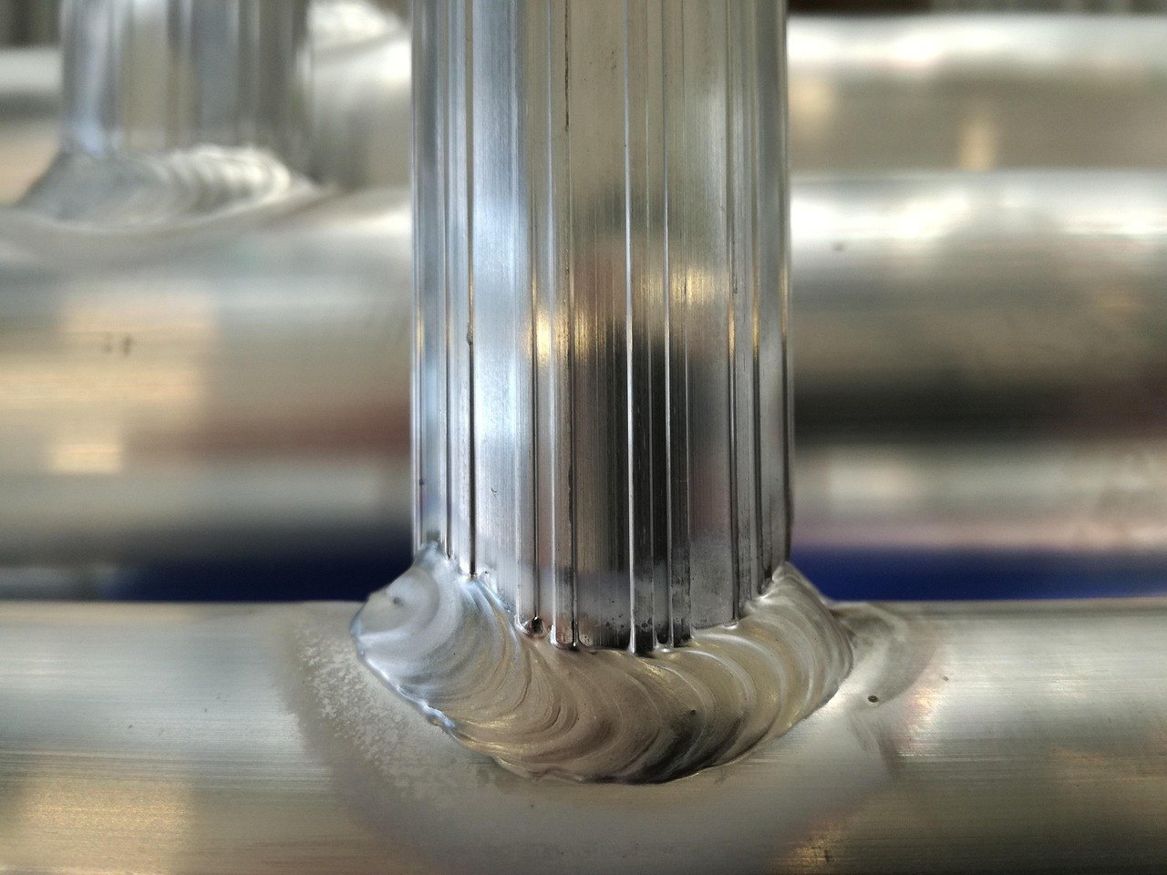
The physical place to check is the weld toe, where the weld meets the plate surface. The model places a probe beside every node of the junction line, at the toe distance along each side, and reads the stress there from the element it falls in. The weld legs come from the job's inputs. The strip between the line and the toe is the weld zone: it is drawn on the contour plot, but no check is made in it.
In our checks against an ASME PTB-3 example and an axisymmetric solid model, PL read at the toe agreed to between −7 % and +3 %. Read on the intersection line, the same stress was 32 % to 67 % high.
Why the P+Q range takes the larger value
The toe is right for the primary checks, but it has a weakness for the secondary one. With no weld stiffness, the shell model under-reads the structural bending at the toe: in our studies by 13 % on one PTB-3 stress classification line. The value at the intersection line, linearised from the forces and moments that cross it, does not have that problem. It is set by equilibrium, it does not depend on the mesh, and in our studies it came within about 3 % of a solid model's value at the toe.
So the model splits the work. Pm, PL, PL+Pb and the local-failure check are read at the toes. The P+Q range takes the larger of the toe value and the line value. The report states the toe distances it used on each side.
What the shell model does not give
Peak stress is the part that comes from the notch itself: the weld profile, the toe angle, the local shape. Division 2 uses it only for fatigue. A shell model cannot produce it, because the notch is not in the model. There are two ways to get closer to it.
- A solid model with the weld in it. The workbench has an optional solid detail of the junction: the fillets meshed as 45° triangles, the block cut 2.5√(R·T) beyond the weld and driven by the shell solution, with stress classification lines through the wall.
- A fatigue method built for welds. The structural-stress method of Division 2 works from the mesh-insensitive membrane and bending at the weld line, which is the quantity a shell model does give.
Fatigue in FEXLA today
When a job carries load cycles with a count, the workbench runs Division 2 fatigue screening and then fatigue analysis along each weld line, on both faces, by the structural-stress method and by the elastic method with a notch factor. Where a P+Q range exceeds SPS, ratcheting is checked by the Bree diagram. These checks are built and in early access. How fatigue and Bree are offered on the application cards is still being decided, so they are not described here as a finished feature.
Whatever the method, a model of one attachment and a piece of shell answers for that attachment's welds only. It does not see cycling at other nozzles, supports or closures, or cyclic loads that never reach the attachment. Joint misalignment and weld peaking are not modelled either.
Where it stops
- 01The shell model has no weld geometry or weld stiffness. The weld zone between the intersection line and the toe is plotted, not checked.
- 02Peak stress at the toe notch is not resolved. It needs a solid model with the weld or a fatigue method of its own.
- 03A fatigue answer from a local model covers that attachment's welds only. Joint misalignment and weld peaking are not modelled.
- 04The finite-element results, the solid detail and the fatigue checks are early access and under verification. Until that is finished they are not a source of design values.
Try it in FEXLA
The Nozzle loads card runs WRC 537 and builds the shell model of the same nozzle, which reads its junction stresses at the weld toes.
Open the cardReferences
- ASME Section VIII Division 2, Part 5: 5.5.4 fatigue analysis, and Annex 5-A, linearisation of stress results.
- ASME PTB-3, Section VIII Division 2 example problems, as cited in the solver's notes.
Method notes this draws on
Next post: Where to place a stress classification line at a nozzle
Educational article. It explains principles and is not design guidance; follow your governing code and edition.